|
|
|
Commins AutoTight® Rod Holdown System |
|
Calculate the Differential Loads:
Calculate the Differential Load (incremental uplift force). The
differential load is the difference between the uplift load at each
level vs. the level above. This load transfer point is where the
uplift load is transferred into the structure. This may happen on
every level or may skip levels.
(Note: if a load transfer point is used on every level, fewer
trimmers will be used and plate sizes can be smaller. However, more
take-up devices and plates will be needed. If floors are skipped
then fewer take-up devices are required but rod size and trimmers
may be increased.) |
|
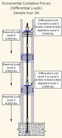
Sample: Run 3A uses R6 rod (3/4”) on level 1 and R5
rod (5/8”) on levels 2 and 3. Take-Up devices are always installed
at levels where the threaded rod size changes.
1. In sample Run 3A, the differential load transfer will occur at
level 1 and level 3.
2. The differential load at level 1 is the difference between level
1and 2. (8,000-5,500 = 2,500 lbs.)
3. The differential load at level 3 is the remaining run load.
(8,000 – 2,500 = 5,500 lbs.)
Note: Load transfer points are always on the floor of the story
above. Loads are carried through the floor and into the story below.
(Exception: when a header is used with short trimmers in a wall,
usually at the top floor)
After the differential load information is put into the table the
balance of the runs can be determined. |
 |
|
|
|
|
Sample Load Justification (Table B) |
|
|
|
|
|
|
3A |
|
|
4A |
|
|
5A |
|
|
|
|
|
Reqd |
Tension |
Diff. |
Reqd |
Tension |
Diff. |
Reqd |
Tension |
Diff. |
Story |
Estimated |
|
Level |
Load |
Load |
Load |
Load |
Load |
Load |
Load |
Load |
Load |
Heights |
Wood |
|
|
lbs |
Rod |
Plate |
lbs |
Rod |
Plate |
lbs |
Rod |
Plate |
|
Shrinkage |
|
5 |
|
|
|
|
|
|
3,500 |
6,136 |
6,000 |
10" - 0" |
0.25" |
|
|
|
|
|
|
|
|
|
R5 |
|
|
|
|
4 |
|
|
|
3,500 |
6,136 |
6,000 |
6,000 |
6,136 |
|
10' - 0" |
0.25" |
|
|
|
|
|
|
R5 |
|
|
R5 |
|
|
|
|
3 |
3,000 |
6,136 |
5,500 |
6,000 |
6,136 |
|
10,000 |
15,708 |
9,500 |
10" - 0" |
0.25" |
|
|
|
R5 |
|
|
R5 |
|
|
R8 |
|
|
|
|
2 |
5,500 |
6,136 |
|
11,000 |
15,708 |
9,500 |
15,500 |
15,708 |
|
10' - 0" |
0.25" |
|
|
|
R5 |
|
|
R8 |
|
|
R8 |
|
|
|
|
1 |
8,000 |
8,836 |
2,500 |
15,500 |
15,708 |
|
24,500 |
24,544 |
9,000 |
10" - 0" |
0.25" |
|
|
|
R6 |
|
|
R8 |
|
|
R10 |
|
|
|
|
<< Back
Next>>
Key Structural Information
Organizing the Runs
Specifying the Rod Size
Specifying the AutoTight® Components |
Download -
Specifying
the AutoTight® System . pdf - (4
pages, 111.1k)Acrobat Reader is required to view the
material.

|
|
|
Contact
Webmaster with questions
or comments |
Copyright 2005
Commins Manufacturing, Inc., Friday Harbor, WA 98250, Tel (360) 378-9484 |
| |
AutoTight® Rod Holdown
Systems and components are covered by one or more of the following U.S.
Patents 6,390,747; 6,585,469; 6,625,945, other patents both foreign and
domestic are pending. |
|

