|
|
|
Commins AutoTight® Rod Holdown System |
|
Specifying the Rod Size:
Select
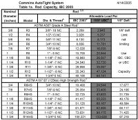
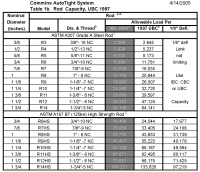
the threaded rod for the required load on each level. Use Commins
Autotight® Table 1a for the 2003 IBC and Table 2a for the 1997 UBC.
(Note the rod diameter is designated in 1/8th of an inch. R6 is
6/8th inch or ¾”).
|
Table 1a: AutoTight® Holdown System
2003 International Building Code (IBC)

|
Table
1b: AutoTight® Holdown System
1997 Uniform Building Code (UBC)
 |
|
Table (1a & 2a) explanation: The table is divided into three
sections. The rod is specified on the left side. The plates are
specified in the center and the take-up devices are on the right.
Select the rod to carry the uplift load on all floors above each
load transfer point. Select the plate based on the differential load
at each load transfer point. Select the AT Auto Take-Up based on the
differential load and the rod diameter over which it fits.
|
|
|
|
|
Sample Load Justification (Table A) |
|
|
|
|
|
|
3A |
|
|
4A |
|
|
5A |
|
|
|
|
|
Reqd |
Tension |
Diff. |
Reqd |
Tension |
Diff. |
Reqd |
Tension |
Diff. |
Story |
Estimated |
|
Level |
Load |
Load |
Load |
Load |
Load |
Load |
Load |
Load |
Load |
Heights |
Wood |
|
|
lbs |
Rod |
Plate |
lbs |
Rod |
Plate |
lbs |
Rod |
Plate |
|
Shrinkage |
|
5 |
|
|
|
|
|
|
3,500 |
6,136 |
|
10" - 0" |
0.25" |
|
|
|
|
|
|
|
|
|
R5 |
|
|
|
|
4 |
|
|
|
3,500 |
6,136 |
|
6,500 |
6,136 |
|
10' - 0" |
0.25" |
|
|
|
|
|
|
R5 |
|
|
R5 |
|
|
|
|
3 |
3,000 |
6,136 |
|
6,500 |
6,136 |
|
10,000 |
15,708 |
|
10" - 0" |
0.25" |
|
|
|
R5 |
|
|
R5 |
|
|
R8 |
|
|
|
|
2 |
5,500 |
6,136 |
|
11,500 |
15,708 |
|
16,000 |
15,708 |
|
10' - 0" |
0.25" |
|
|
|
R5 |
|
|
R8 |
|
|
R8 |
|
|
|
|
1 |
8,000 |
8,836 |
|
17,500 |
15,708 |
|
25,000 |
24,544 |
|
10" - 0" |
0.25" |
|
|
|
R6 |
|
|
R8 |
|
|
R10 |
|
|
|
|
|
Example run 3A (level 1) requires 8,000 lbs. capacity. Select an R6
rod from ICC Table 1a with the allowable load of 8,826 lbs. Levels 2
and 3 require 5,500 lbs. and 3,000 lbs respectively. Select an R5
rod from ICC Table 1a. The allowable load is 6,136 lbs. R5 rod will
be used for the balance of the run to simplify the installation and
design.
|
<< Back
Next>>
Key Structural Information
Organizing the Runs
Calculate the Differential Load
Specifying the AutoTight® Components |
Download -
Specifying
the AutoTight® System . pdf - (4
pages, 111.1k)Acrobat Reader
is required to view the
material.

|
|
|
Contact
Webmaster with questions
or comments |
Copyright 2005
Commins Manufacturing, Inc., Friday Harbor, WA 98250, Tel (360) 378-9484 |
| |
AutoTight® Rod Holdown
Systems and components are covered by one or more of the following U.S.
Patents 6,390,747; 6,585,469; 6,625,945, other patents both foreign and
domestic are pending. |
|


