|
Installation Guide - Rod System |
|
Rod System Install
AT Device Install |
|
Header Install
Trimmer Install |
Embedment Install
Beam Start Install |
The installation procedures described are
recommendations, based on our experience and input from field
installers. Every project is a little bit different and we encourage
additional input to continually improve our system's installation.
Always consult the AutoTight® supplied plans for the correct
materials, information and details for the runs to be installed.
|
 |
|
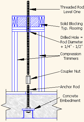
• Install the first level Shearwall over the
Embedment Anchor Rod.
•
Drill a hole 1/4" - 1/2" larger than the diameter of the threaded rod to be
installed. The hole is to be located directly above the anchor bolt.
•
Use the AutoTight®
stud layout drawing or a plumb bob to locate the
hole position. The rod may be offset a maximum of 2" per 10' floor
height, if required. |
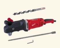
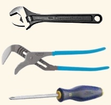
Recommended Tools

1/2" Right Angle Drill, 17" Ship Auger
and 18" Bit Extension

Crescent Wrench, Channel Locks
and Phillips Screwdriver |
|
• Install the proper size and length first level
rod for the run by feeding it down through the previously drilled
hole from the level above.
•
Install the proper coupler nut approximately halfway onto the anchor
rod.
•
Thread the rod into the coupler nut insuring that the threaded rod
is fully seated at the midpoint of the coupler.
|

Coupler with
Threaded Rod
Fully Seat at
Mid-Point
of the Coupler |
 |
|
• Drill the bottom plate for the next level Shearwall to match the rod diameter from the level below. Locate the
position of the hole using the stud layout per the plans or matching
the lower level layout.
•
After placing the Shearwall in place, drill a
hole into the top plate a 1/4" - 1/2" larger than the diameter of the threaded rod for the
level. The hole maybe smaller to match the rod for the level.
•
The hole is to be located directly above the installed rod
centerline from the lower level. The rod may be offset a maximum of 2" per 10'
floor height, if required. |
•
Install the Bearing Plate, AT Device, Washer and Nut, if required on
the Bottom Plate of the Shearwall. AT
Device Installation
•
Install the Coupler Nut or Reducer Coupler Nut as required.
•
Repeat the level install process for the next level. |
|
Rod System Install
AT Device Install |
|
Header Install
Trimmer Install |
Embedment Install
Beam Start Install |


