IIC ESR
ALL TAKE-UP DEVICES ARE
REQUIRED TO HAVE A CURRENT
ICC EVALUATION REPORT
ATS components
The Tie-Down system shall be designed per the 2018 IBC for strength, elongation and shrinkage and shall follow applicable ICC-ES Acceptance Criteria as follows:
The specification may require fine detailing (elongation and shrinkage) in some areas. This is needed for code required precision.
AC155 Acceptance Criteria for Hold-Downs (Tie-Downs) Attached to Wood Members, May 2015.
Conventional Tie-Downs are often used in combination with Rod Tie-Down Systems. This AC includes often missed design criteria for Standard Tie-Downs.
AC316 Acceptance Criteria for Shrinkage Compensating Devices. March 2015.
All TUDs require an ICC-ES Report that details strengths, capacities and product movements under load. Having a code acceptance allows the use of TUDs, but only if the details shown in the report are followed.
AC391 Acceptance Criteria for Continuous Rod Tie-Down Systems used to resist Wind Uplift. March 2015. This Acceptance Criteria defines the correct method to determine rod elongation.
Uplift forces are as shown in the holdown schedule.
Material Strengths shall follow AISC 360, 14th edition. Allowable Strength Design (ASD) or Load and Resistance Force Design (LRFD) shall be followed. (Specify one).
Most designers make their own holdown/tie-down schedule. Figure 1 shows a sample. Some designers show the required uplift loads on the plans and leave it to the tie-down company to determine the runs. Either method can be used.
Always compare the strength numbers with the AISC. Even if you specify that the tie-down system shall follow the IBC 2018, some suppliers are not following AISC 360 14th edition. Depending on the supplier their methods overstate rod strength by 11 to 16%. Even worse, some suppliers switch the method back and forth from one method to another. Beware.
System Strength shall be limited by the lesser of: threaded rod tensile strength, bearing plate compressive strength, hold-down strength or shrinkage compensator (TUD) strength.
Elongation Per the National Design Specification (NDS) total elongation between reaction points shall be limited to 0.200″or less (or specified by designer). See the NDS (SDPWS-2015 Eq. 4.3-1). Designers often specify different elongation limits on different floors or runs to control drift. (Example: System elongation is 0.188″ per floor, except runs with * are 0.125″ per floor.)
System elongation shall include all tension elements including: shrinkage, rod, bearing plate, hold-down, and TUD. ΔR + ΔA
System Elongation is often understated by leaving one or more of the required elongation components off the computations. Logic and the NDS require all items under load are included.
System Δ = S Δ Rod 1+Δ Rod 2+Δ Rod 3 etc. +Δ Plate+TUD ΔT = ΔR + Δ A(PD/PA). (ICC ES AC316)
All elongations are adjusted based on loading. Exceptions: Shrinkage is added in full. If a TUD is used and sized for the expected shrinkage, shrinkage is eliminated and is considered as 0.000”. TUD ΔR is always added in full.
Rod elongation is per ICC ES AC391 = ΔL = PL/An29,000,000
Some designers or suppliers use the Gross area for rod elongation but the code requires using the net area of the rod. Depending on diameter and thread, using the gross area will understate elongation by 26 to 36%.
Tie-Down Shrinkage Compensators shall have a current ICC-ES report. Only screw type shrinkage compensators shall be used.
Ratchet TUDs often have 60 times ΔR deflection compared to screw TUDs. Systems with ratchet TUDs often require an increase in rod diameter to meet drift limits.
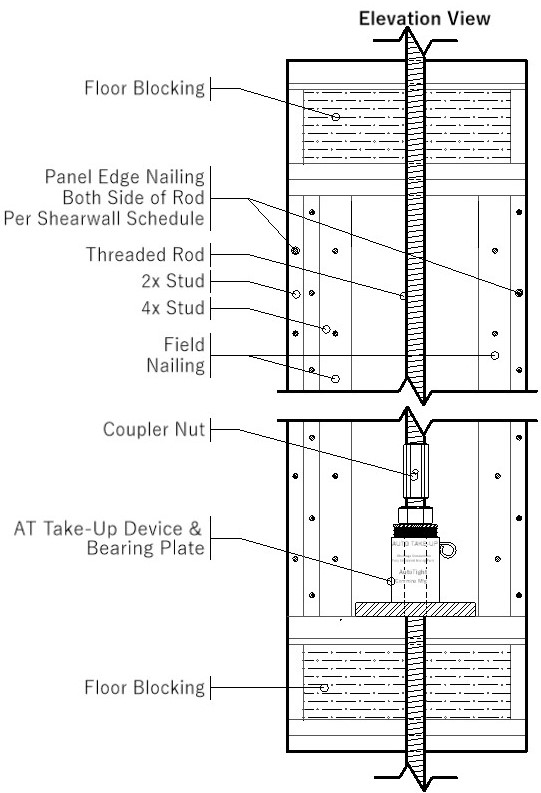
A shrinkage compensator (TUD) shall be used at each reaction point. TUDs shall accommodate cumulative shrinkage of: 1/4″, (or 3/8) per floor.
Straps shall not be used with vertical connections. (See strap shrinkage photos.)
Specify wall widths. 4X, 6X or 8X. Rod systems require rod and wood to compete for the same location at the end of the walls. Six-inch (5-1/2″) walls are required for wide steel bearing plates. Consider 8″ (7-1/2″) walls for heavy reactions. State the minimum number of studs between the end of the wall and the first tension rod.
Append a tie-down schedule. Include tension and compression loads, floor heights, floor levels, and cumulative shrinkage. As an alternative, provide plans that specify uplift loads at every reaction.
Loads shown in this table are cumulative rod loads. Compression loads include structure gravity loads plus uplift loads induced by lateral loading.
Specified Compression Posts shall be designed for the indicated loads (kips) as specified on the tie-down schedule. Specified compression post loading includes combined gravity and holdown reaction loads.
(This is the most efficient way to specify posting. If this method is not used provide specific requirements!)
Traditional Holdowns may be combined with continuous tie-down systems, but TUDs should be used in all holdowns and drift compatibility from traditional HD’s must be considered when mixing traditional and continuous tie-down systems. All traditional HD’s shall have a TUD installed.
Mudsill Plates shall be provided on the first-floor wood plate. (If not required specify: “Mudsill plates are not required.”
There are two reasons to use a Mudsill Bearing Plate.
-
If a through deck connection is used the “mudsill” plate on top secures the Under deck “Uplift plate”.