DESIGNING A HOLDOWN: COMPARATIVE ANALYSIS
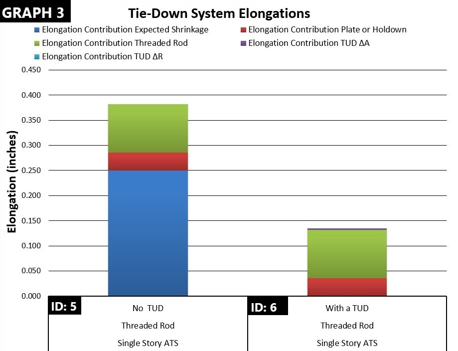
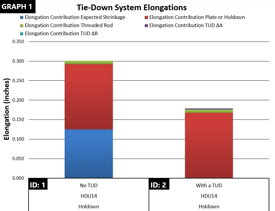
Weather you use standard holdowns, straps or continuous rod tie-downs, all systems should be designed in the same manner; all components must be included, (this includes shrinkage) and all components must follow the same code provisions as shown in the IBC. The following six systems compare and contrast the performance of holdowns with and without a TUD and compare that performance to a rod tie-down. When a screw type TUD is used system elongation can be changed or tuned to within 0.001” inch.
OVERVIEW
-
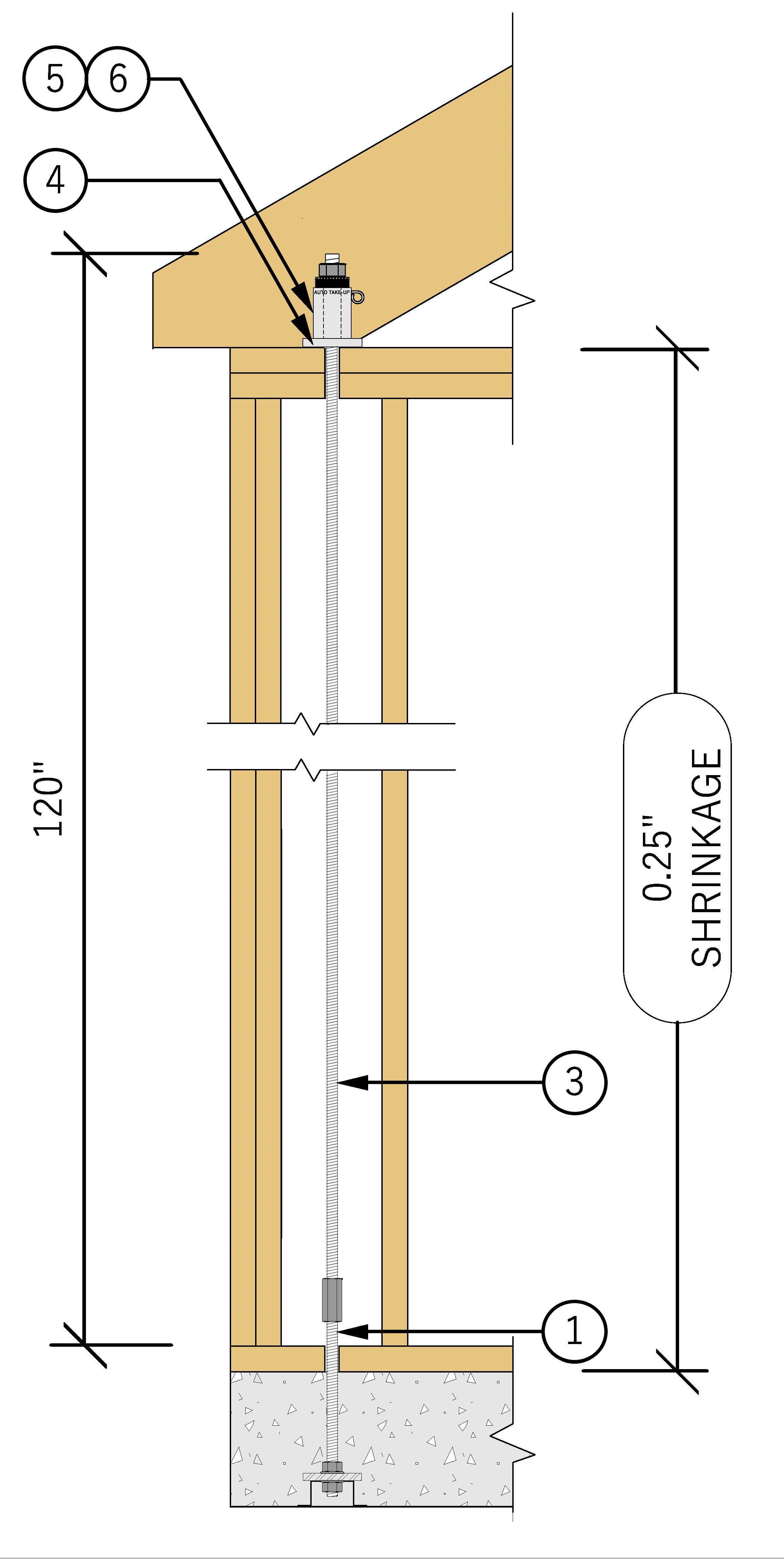
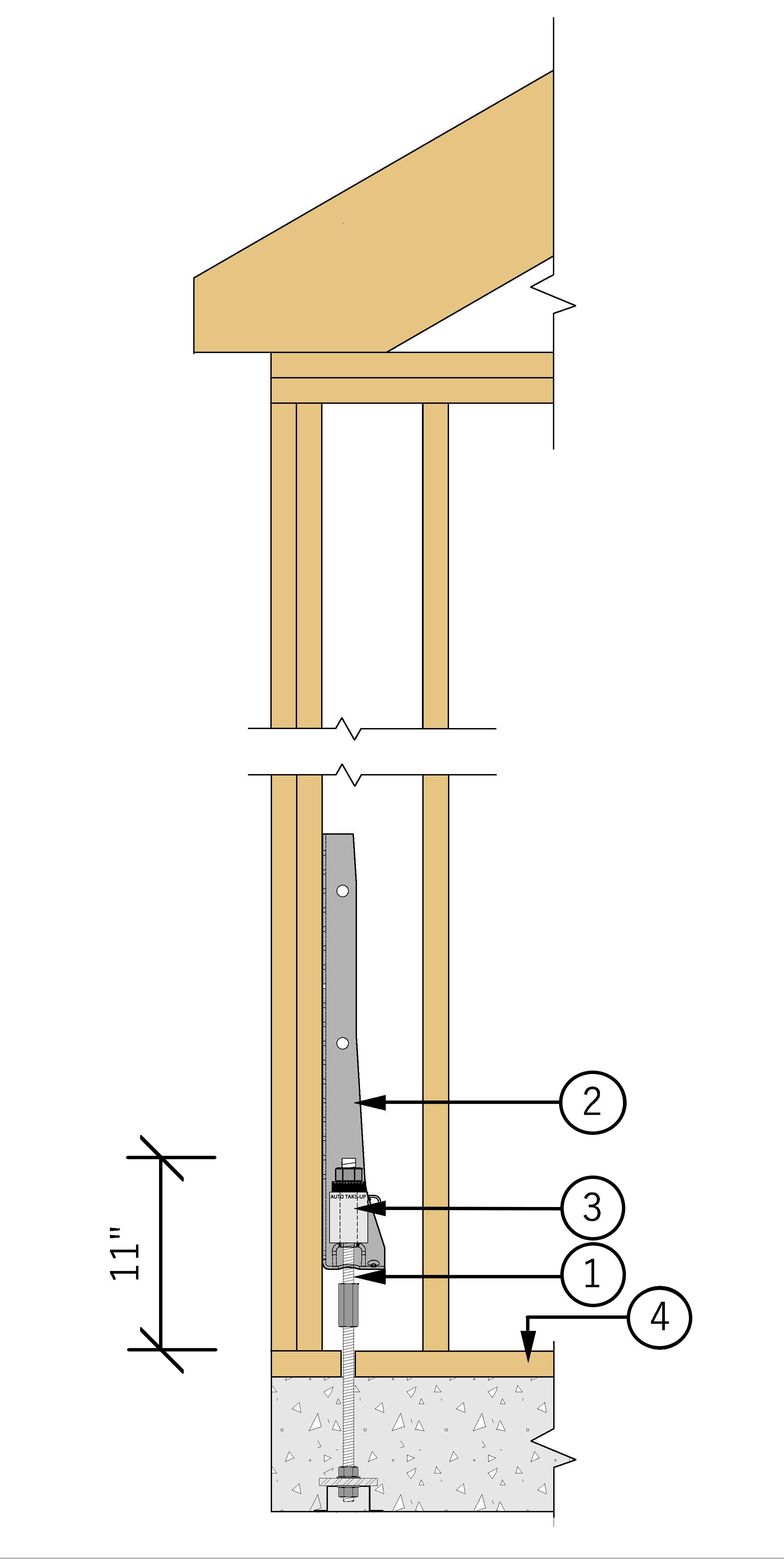
All comparative systems use a 14,000 lb. design load and were installed on floor heights of 10’. Note, straps are not included, because they cannot handle shrinkage.
-
Standard Holdowns are shown first. These are shown as ground floor and second floor installations .
-
Ground floor shrinkage is assumed as 1/8”. All other shrinkage is assumed as ¼”.
COMPONENTS
-
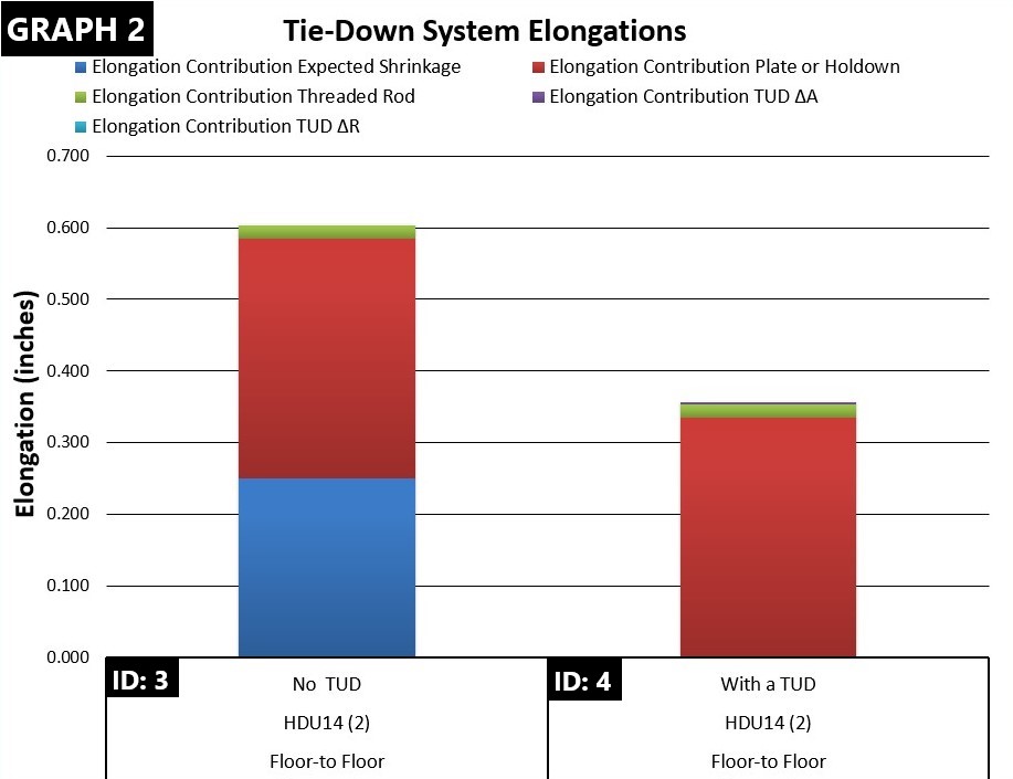
TUD deflection includes both ΔA and ΔR. TUD deflection is for a screw type TUD only. Ratchets have 10 to 40 times the deflection. (See section 2 vetting). Note that for screw type TUDs movement is so low that it does not show on the graph.
-
Rod elongation varies widely depending on the length under load.
-
Plate or HD Δ contribution demonstrates the deflection of one or two holdowns and between holdowns and plates.

THIS TABULATION ILLUSTRATES THE THE DATA PRESENTED IN THE THREE GRAPHS BELOW
GRAPH NOTES:
-
Deflection limit 0.200″
-
Limit applies to all conditions
-
Deflection sum includes all components per NDS 4.3.3.
TABLE NOTES:
-
Expected shrinkage of 0.125 to 0.250″ was added to system elongation.
-
Shrinkage shown as 0.250″ was mitigated by use of an AT8A-1.5 Take-Up Device and NOT added to the total elongation.
-
TUD ΔR deflection shown as 0.000″ and TUD ΔA deflection 0.003″ are too small to show on the chart. Competitiver TUDs may have 0.050″ to 0.125″ deflection. Excessive operating looseness has been know to cause sudden failer in a multi-level system.
LETS GET STARTED
STANDARD HOLDOWN CONNECTION
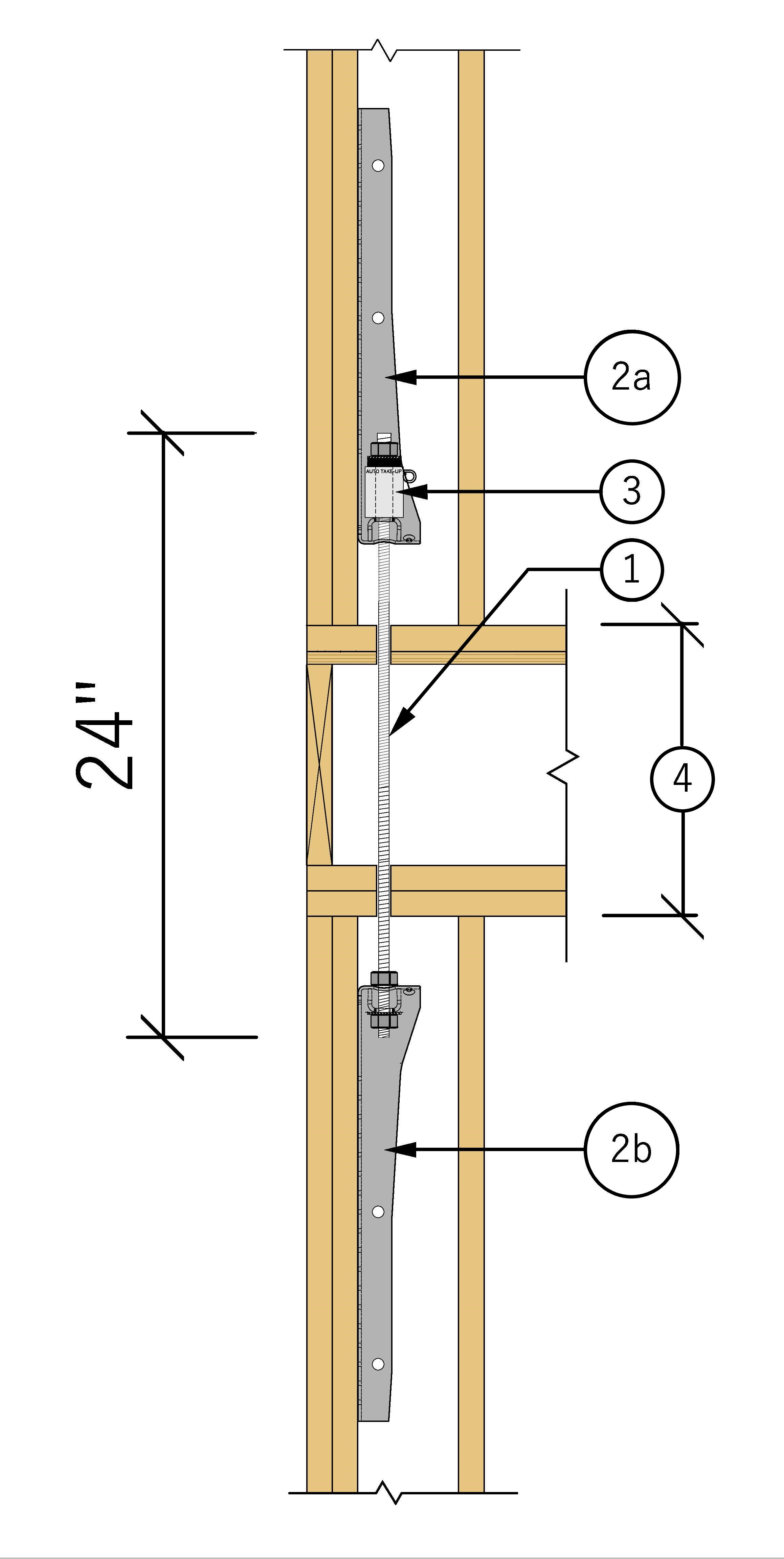
STANDARD FLOOR-TO-FLOOR CONNECTION
SINGLE LEVEL ATS CONNECTION
