Technical Note 11: Anatomy of a Tie-Down
 ICC Evaluation Service has added a maximum limit of 0.200" for Tie-Down Systems.
The following specification includes the new elongation limit. It is a good starting
point for specifying any tie-down system. Modify it as you like.

Tie-Down System Specification
The Tie-Down System shall be the continuous rod system as manufactured by Commins Manufacturing Inc. with ICC ESR#1344 and/or COLA RR 24580. With the written consent of the Engineer-of-Record, other systems may be substituted provided they meet the following:
1. The system shall be designed for strength and elongation per the local code.
2. System elongation between reaction points shall be limited to 0.200".
System elongation shall include all tension elements including:
rod elongation, bearing plate compression, shrinkage and shrinkage
compensator, delta A (DA) and delta R (DR).
Runs specified with an (*) shall be limited to 0.125. Common elongation limits include 0.125" and 0.200". Runs with an * limit short wall deflection.
Runs specified with an (*) shall be limited to 0.125. Common elongation limits include 0.125" and 0.200". Runs with an * limit short wall deflection.
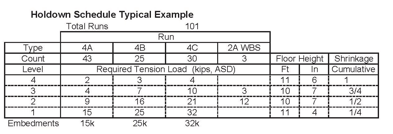
3. Uplift forces and floor heights (carpet-to-carpet) are as shown in the Holdown
Schedule. Forces shown are cumulative (full rod tensile load) ASD
(Preferred) or LRFD forces in kips. (See example page 2).
4. The system shall accommodate a minimum out-of-plumb of 3" per 10' floor.
5. The system shall provide a minimum cumulative shrinkage compensation of:
¼" per floor (manufactured wood), ½" per floor -(solid sawn)
6. Each reaction point shall be connected to the rod through a shrinkage compensator.
7. Straps may not be used with vertical connections
Commentary: We can supply systems with elongation limits as low as 0.100" for rod and 0.125" for the system. Tight elongation limits are difficult to achieve but are do-able. The most common error is to include rod elongation only and neglect the rest of the system. Components such as bearing plates, shrinkage compensators and hold-downs can double or triple actual elongation. Unless a jurisdiction requires both a rod and system elongation limit use a full system elongation limit only. We suggest that a tight system limit will provide the best balance between cost and performance.
Shrinkage: Typically shrinkage is specified at 1/4" per floor with premium material (wood I joists, lvl etc) and 1/2" per floor for solid sawn materials. For additional guidance see Tech Note. TN 15 Building Shrinkage and Settling
As of January 1, 2012, ICC ES requires shrinkage compensating devices to include the deflection at the allowable load (Delta A) and average travel and seating increment (Delta R). See Technical Note TN 10 Anatomy of a Tie-Down for more information. Because Delta R must be added in full, the analysis of tie-down systems has become more difficult. Delta R for Shrinkage compensating devices varies from 0.000" (AutoTight) up to 0.080" (Competitive Product).
Runs are designed and combined using a simple run sort. Each run is identified by location and by floor. Runs are sorted and grouped by similar loads. More run types will result in a lower material cost per run but will complicate placement raising labor cost. Our recommendation: aim for 5 or 6 different run types if possible.

Run Type ID: List the run types by the number of floors then A, B, etc. WBS is a wood beam start.
Run Count: Run count quantities are seldom provided by the EOR. If a count is supplied contractors will receive a more accurate and competitive bid.
Elongation Limit: 0.200” Code: IBC 2009 Design Shrinkage: 1/4” /floor
Floor Height: (Carpet-to-carpet) Total distance between floors including floor and wall heights.
Embedments: per plans
For a complete discussion See Technical Note 17. Designing Tie-Down Systems for Strength,
If the specification and holdown schedule is provided most suppliers can design a system for strength, elongation, and shrinkage. See TN 11b for the results of the system shown.
